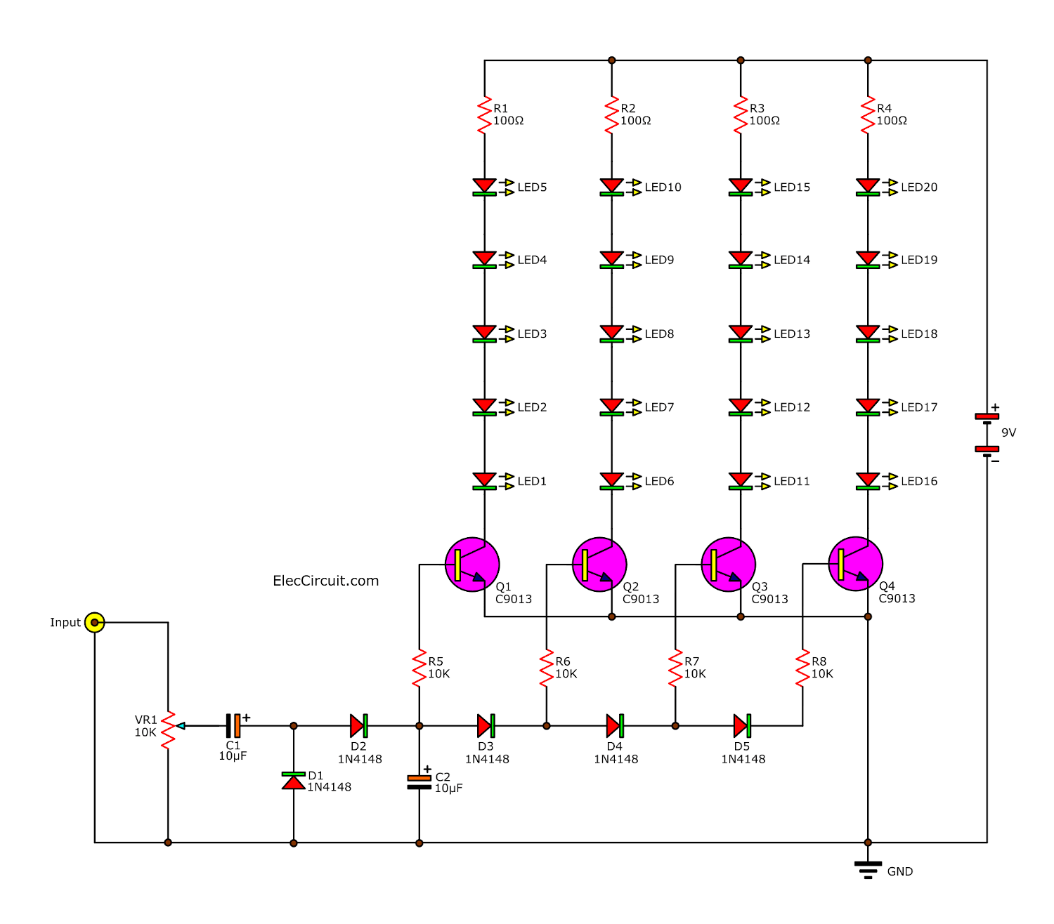
20 LED vu meter schematic Electronic projects circuits
Step 1: Finding the Main IC So in order to make this VU meter, I'll be resorting to al analog circuitry without any Arduino microcontrollers as that would be another project for another time. So the IC of choice is one of LM3914 / LM3915 / LM3916.
Simple VU Meter using 2N3904 Transistor
A volume unit ( VU) meter or standard volume indicator ( SVI) is a device displaying a representation of the signal level in audio equipment. The original design was proposed in the 1940 IRE paper, A New Standard Volume Indicator and Reference Level, written by experts from CBS, NBC, and Bell Telephone Laboratories. [1]
Analog VU meter circuit using transistors
The VU meter and circuit connected to my full vinyl lathe pre-electronics. A 10W amplifier, volume control, the VU meter, inverse-RIAA filter and output to the lathe and headphones. And the circuit, prototyped on a breadboard. The crisscrossing diodes make this a little tricky.
Led Vu Meter Circuit Diagram Wiring Diagram
A VU meter is a device that can visualize the volume of an audio source. In this case, the audio picked up by the microphone is used as the input. The Arduino is employed for its analog-to-digital conversion capabilities. BOM This project was built using the following parts: Part/Qty Perfboard or Breadboard - 1 Arduino Nano Every - 1
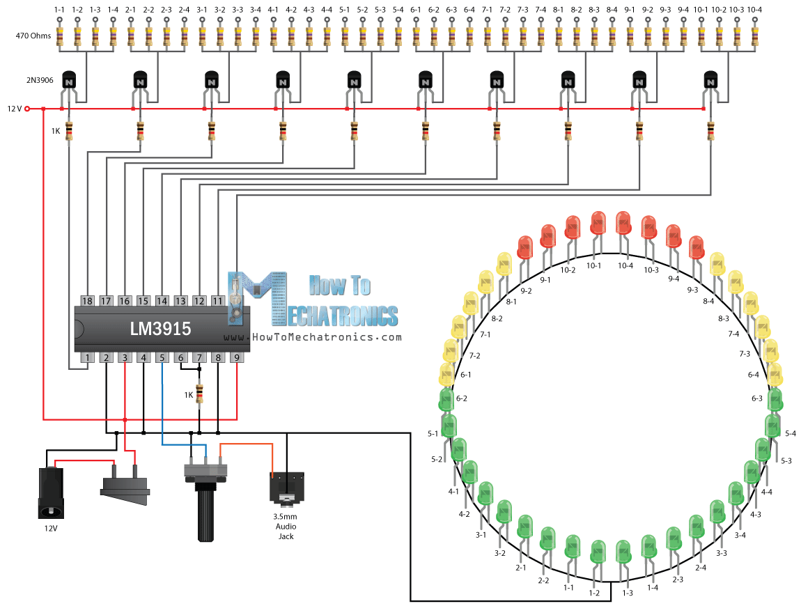
Infinity Mirror Music VU Meter Electronics Project using LM3915 IC How To Mechatronics
The VU meter is a circuit for an indicator of the audio signal strength. The VU meter circuit is usually applied to an amplifier circuit so that the level of audio power can be determined by certain parameter settings which will be displayed in the form of light from the LED.

Lm324 Ic Vu Meter Circuit Diagram
Simple VU-meter circuit test. It's basically a simple display for showing a value. It's originally for showing signal level in audio circuits, but there's no reason you can't use it to show temperature, rain intensity, light level, or whatever other value you are measuring. In the video above, I added a potentiometer as a voltage.
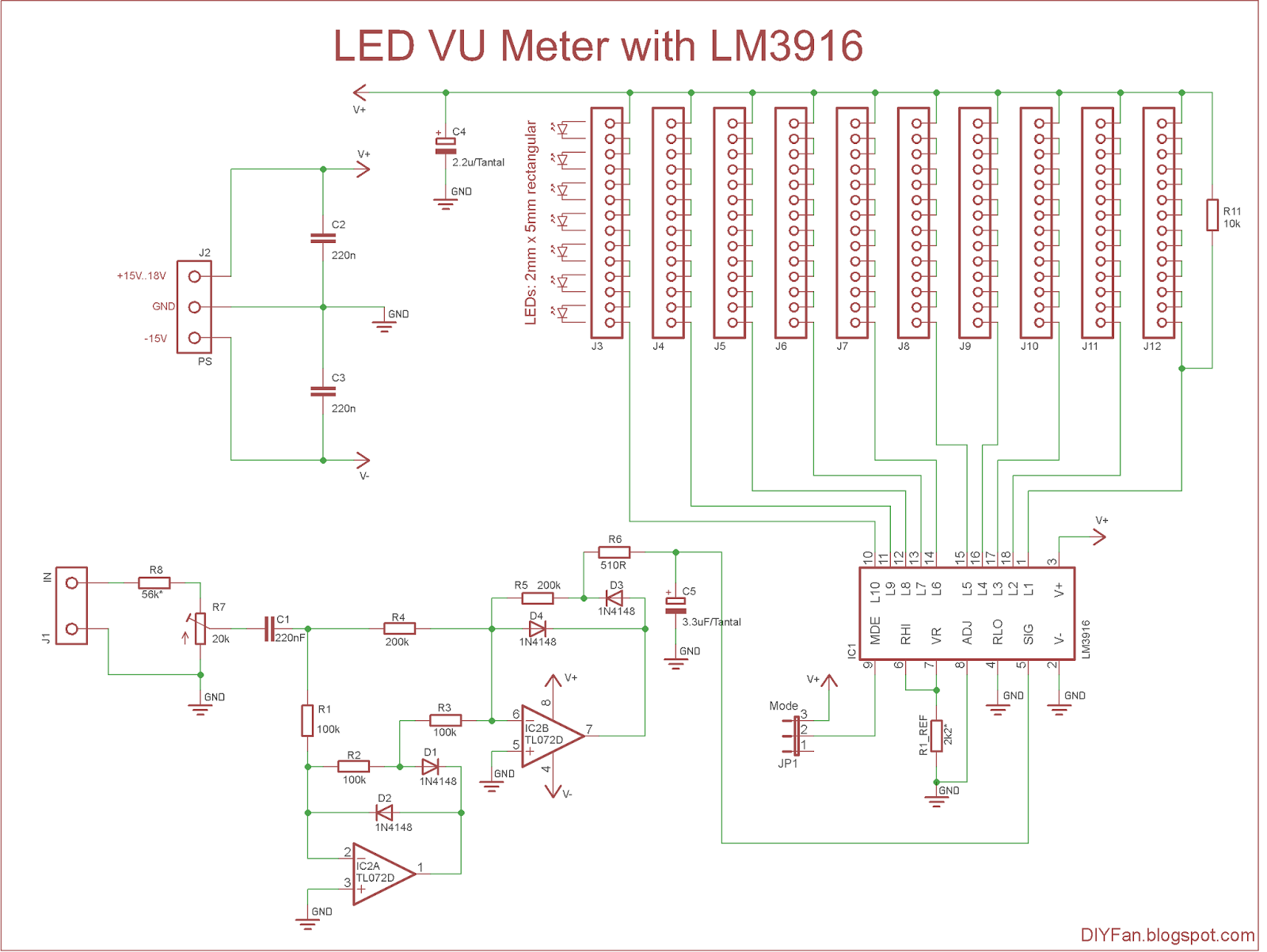
LED VU Meter with LM3916 ElectronicsLab
VU meter or a volume unit meter circuit is a device used for indicating the music volume output from an amplifier or a loudspeaker system. It may be also considered as a device for displaying the PMPO of the amplifier at a particular volume setting.

Simple VU Meter Circuit Jeff Thompson
A volume unit or VU meter is a device that shows the audio level in audio devices from which a user can maintain a certain audio level and get rid of overloading the output. This circuit is very useful and inexpensive as it is using only a few components such as a transistor, diodes, resistors, capacitors, potentiometer, ampere meter, etc. Buy Now
VU Meter 1 circuit diagram and instructions
VU, or Volume Unit, meters are a way of measuring the level of an audio signal. They measure the an average of the signal they are presented with, not the peak level or the RMS level, which is displayed in decibels in respect to a preset level.
Simple LED VU Meter Circuit
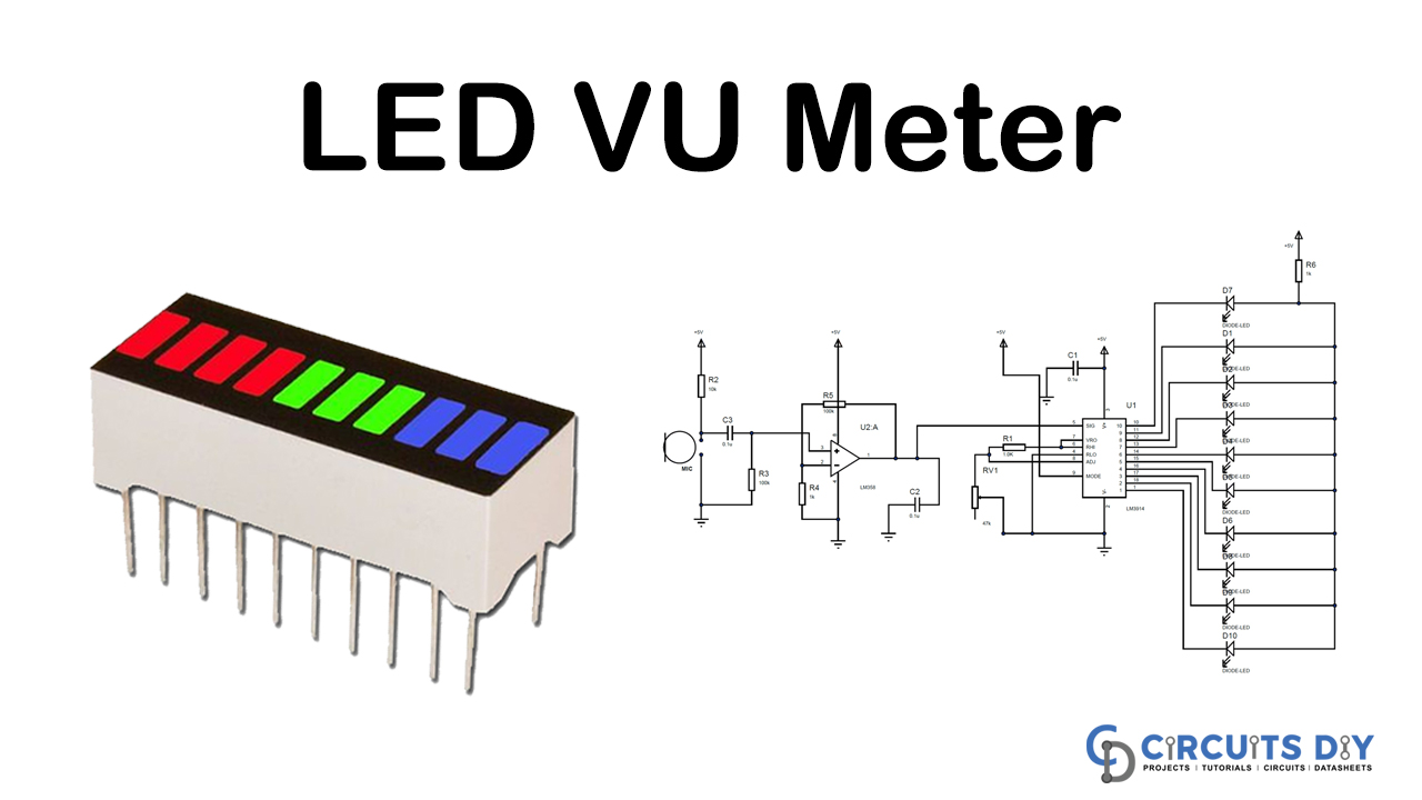
More About Pro Maker_101 » In this project, i will show you how to make a simple & easy Vu Meter or Audio Meter using LM3915. What is a VU meter circuit? A VU meter is also an audio Visualizer that has a group of LEDs as dot or Bar display.

Simple VU Meter Circuit Jeff Thompson
Working: This VU meter is very simple, cheap and interesting project for the learner. In this project, we have used four LM358 dual op-amp IC which is easily available in the market and contains two comparator inside. User may also use two LM324 IC which has four op-amps inside, but it will complex the circuit on the Breadboard.

60dB LED VU Meter Schematic Circuit Diagram
Free Shipping Available On Many Items. Buy On eBay. Money Back Guarantee! But Did You Check eBay? Check Out Top Brands On eBay.
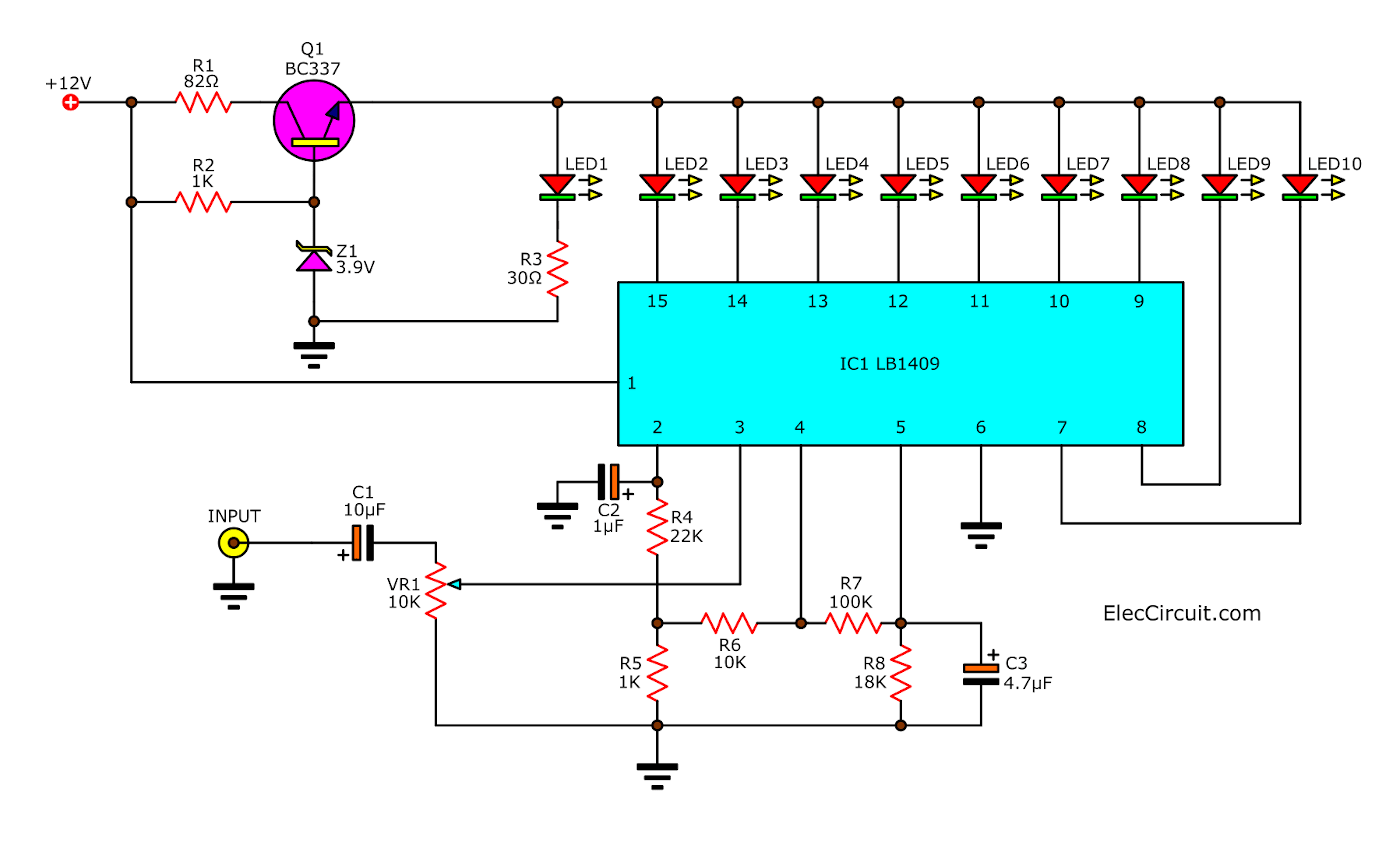
Sound level meter circuit using LB1409
VU meters are basically used with the Amplifiers and audio systems to analyze and display the audio spectrum. The LED dot or bar display lights up LEDs-high to low showing the level of the pitch with matching the pattern of bass going high or low. Here in this article, I am going to discuss a VU meter Circuit using the LM3915 IC. Read more.
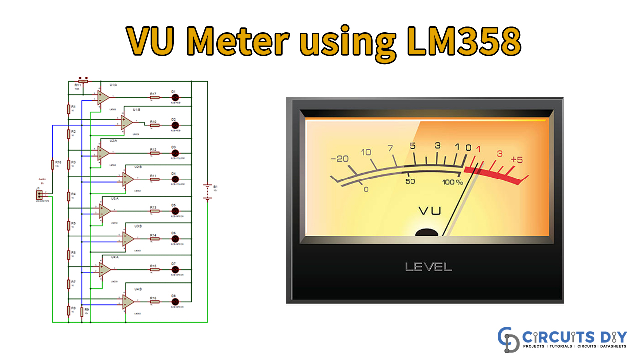
Simple VU Meter Circuit using LM358
Today I am going to make a VU Meter circuit using only one transistor.In this VU Meter I will use 2N2222A Transistor.This VU Meter is not good as compare to 3915 IC VU Meter. Let's get stated, Add Tip Ask Question Comment Download. Step 1: Take All Components As Shown Below. Components required - (1.) Transistor - 2N2222A x1
Analog LED VU meter circuit using transistors
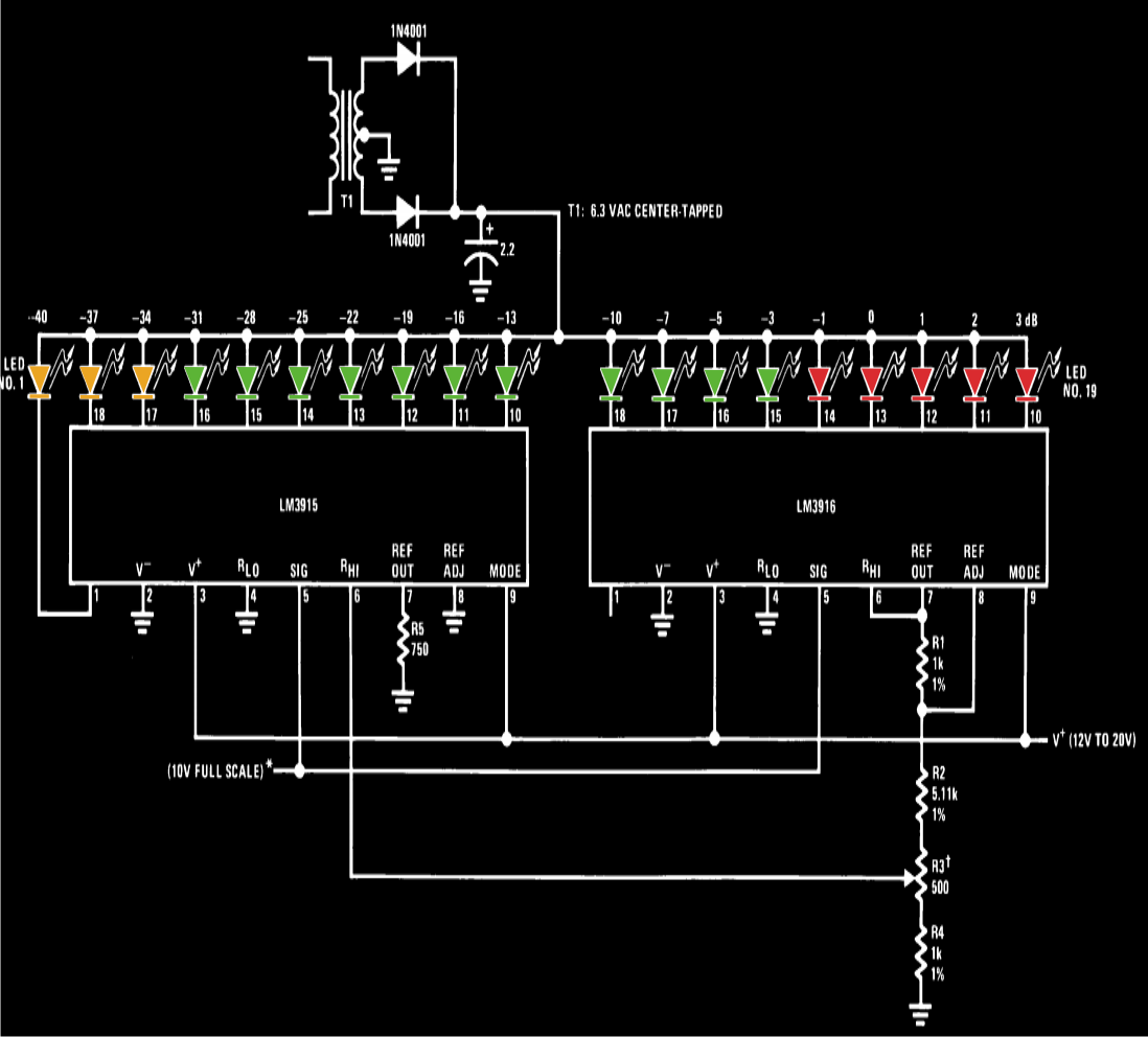
Analog VU meter schematics Last Updated on: November 25, 2021 by Apichet Garaipoom Let's use two simple Analog VU meter schematics. If we take the amplifier connected to the speakers. It is very dangerous.If your amplifier has a higher power than the limits of the speaker. It may make a very bad sound.
LED Vu meter circuit (LM3914) Amateurbuilt.
A simple circuit The basic idea is to use the logarithmic characteristic of diodes to obtain a logarithmic response of an electromechanical microammeter. The circuit is shown below and is really very simple. It's based on a standard 200 μA microammeter which is very very common for this kind of applications.